Receiver Sections:
RF tuning & amplification:
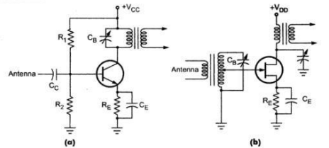
RF amplifier provides initial gain and selectivity. RF amplifier is a simple class A circuit. This RF stage within the overall block diagram for the receiver provides initial tuning to remove the image signal. If noise performance for the receiver is important, then this stage will be designed for optimum noise performance. This RF amplifier circuit block will also increase the signal level so that the noise introduced by later stages is at a lower level in comparison to the wanted signal. A typical bipolar circuit as (a) and FET circuit as (b) is shown below.
 |
| RF tuning & amplification |
Values of resistors R1 and R2 in the bipolar circuit are adjusted such that the amplifier
works as a class A amplifier.The antenna is connected through coupling capacitor to the base of the transistor.This makes the circuit very broad band as the transistor will amplify virtually any signal picked up by the antenna. The collector is tuned with a parallel resonant circuit to provide the initial selectivity for the mixer input.
FET circuit Fig.(b) is more effective than the transistor circuit. Their high input
impedance minimizes the loading on tuned circuits, thereby permitting the Q of the circuit to be higher and selectivity to be sharper.
Local oscillator:
The local oscillator circuit block can take a variety of forms. Early receivers used free
running local oscillators. Today most receivers use frequency synthesizers, normally based around phase locked loops. These provide much greater levels of stability and enable frequencies to be programmed in a variety of ways.
Mixer or Frequency Changer or Converter:
Real-life mixers produce a variety of other undesired outputs, including noise and they
may also suffer overload when very strong signals are present.
Although very basic non-linear devices can actually perform a basic RF mixing or multiplication process, the performance will be far from the ideal, and where good receiver performance is required, the specification of the RF mixer must be match this expectation.
The basic process of RF mixing or multiplication where the incoming RF signal and a
local oscillator are mixed or multiplied together to produce signals at the sum and difference frequencies is key to the whole operation of the superheterodyne receiver.
There are a number of considerations when looking at the receiver design and topology with respect to the RF mixer.There are many different forms of mixer that can be used, and the choice of the type depends very much upon the receiver and the anticipated performance.
Separately Excited Mixer
Intermediate IF amplifier:
 |
| Two Stage IF Amplifier |
Automatic Gain Control, AGC:
An automatic gain control is incorporated into most superheterodyne radios. Its function is to reduce the gain for strong signals so that the audio level is maintained for amplitude sensitive forms of modulation, and also to prevent overloading. It is a system in which the overall gain of a radio receiver is varied automatically with the variations in the strength of the receiver signal to maintain the output substantially constant.
When the average signal level increases, the size of the AGC bias increases and the gain is deceased. When there is no signal, there is a minimum AGC bias and the amplifiers produce maximum gain. There are two types of AGC circuits. They are Simple AGC and Delayed AGC.
Simple AGC
In Simple AGC, the AGC bias starts to increase as soon as the received signal level
exceeds the background noise level.As a result receiver gain starts falling down, reducing the sensitivity of the receiver. In the circuit, the dc bias produced by half wave rectifier is used to control the gain of RF or IF amplifier. The time constant of the filter is kept at least 10 times longer than the period of the lowest modulation frequency received. If the time constant is kept longer, it will give better filtering. The recovered signal is then passes through capacitor to remove dc. The resulting ac
signal is further amplified and applied to the loud speaker.
 |
| Simple AGC circuit |
Delayed AGC
In simple AGC, the unwanted weak signals (noise signals) are amplified with high gain. To avoid this, in delayed AGC circuits, AGC bias is not applied to amplifiers until signal strength has reached a predetermined level, after which AGC bias is applied as with simple AGC, but more strongly.
 |
| Delayed AGC circuit |
output generated by diode detector is above certain dc threshold voltage. This threshold voltage can be adjusted by adjusting the voltage at the positive input of the operational amplifier.
 |
| Response of receiver with various AGC |
Demodulator:
The superheterodyne receiver block diagram only shows one demodulator, but in reality radios may have one or more demodulators dependent upon the type of signals being receiver.Audio amplifier:
Once demodulated, the recovered audio is applied to an audio amplifier block to beamplified to the required level for loudspeakers or headphones. Alternatively the recovered modulation may be used for other applications whereupon it is processed in the required way by a specific circuit block.


0 Comments
Do leave your comment